
MIL-STD-1275: SPIKES & SURGE GENERATORS
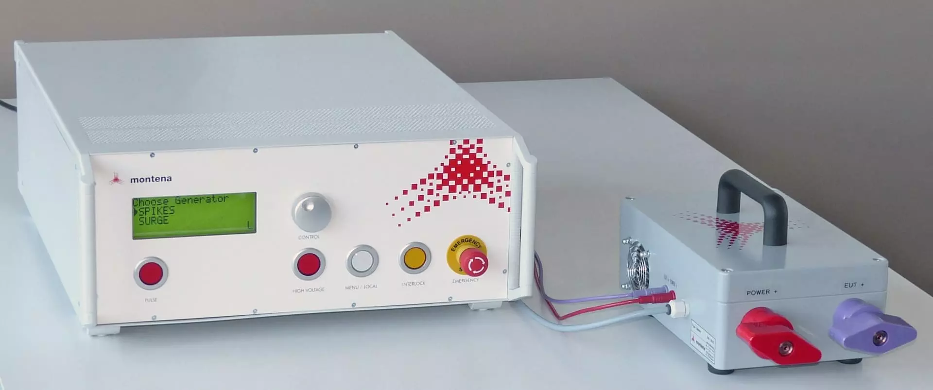
Montena’s PG1275E and PG1275F generators and accessories are specifically designed for conducted susceptibility and transient tests to voltage surge and spikes of 28 Vdc electric circuits in military vehicles according to MIL-STD 1275E and F.
Automatic calibration, reduced testing time
Automatic calculation of energy
Used by many test labs worldwide
Single supplier to offer solutions for versions D, E and F
Montena designs PG1275E and PG1275F generators and accessories for conducted susceptibility and transient tests to voltage surge and spikes of 28 Vdc electric circuits in military vehicles according to MIL-STD 1275E and F.
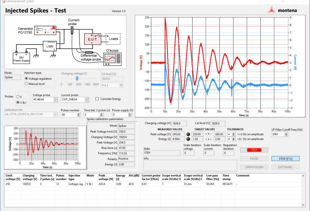
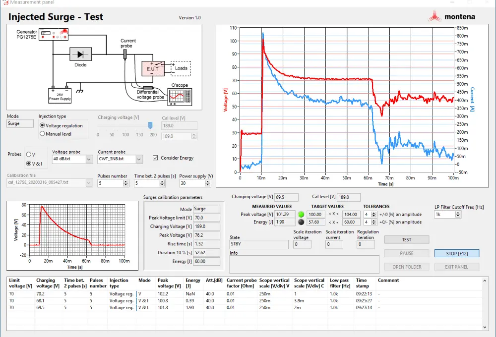
The system includes dedicated control software to assist operators in measuring test parameters, with automatic monitoring of transients energy content. The generator drives a maximum permanent current of 16 A, extendable to 400 A with the optional DM400 external diode module.
DATASHEET & DOCUMENTATION
Access all technical data and resources about our conducted susceptibility generators and test systems and other EMC solutions.
Access detailed specifications
Make informed, confident choices
Contact us for further assistance
FAQ
The PG1275E and PG1275F generators are designed for conducted susceptibility testing of 28 Vdc electrical circuits in military vehicles, in accordance with MIL-STD-1275E and MIL-STD-1275F respectively. They verify the ability of vehicle-installed equipment to withstand two types of electrical transients: injected voltage spikes, which are fast, high-energy transients that can be generated by switching loads or inductive kickback on the vehicle bus; and injected voltage surges, which are longer-duration, high-energy transients typically associated with load dump events or power system faults.
The PG1275E complies with MIL-STD-1275E and the PG1275F with the more recent MIL-STD-1275F. The two versions differ primarily in their surge and spikes parameter specifications: the PG1275E provides an open circuit voltage up to 200 V for the surges and 260 V for the spikes. While the PG1275F provide a lower surge open circuit voltage it has a much high energy capacity (up to 2.6 kJ) and a much lower surge output impedance than version E (see below).
For MIL-STD-1275E : For spikes testing, the open circuit voltage reaches up to 260 V with a maximum stored energy of 4J at maximum charging voltage. The nominal spikes frequency is 100 kHz.
For MIL-STD-1275F : For spikes testing, the open circuit voltage reaches up to 500V with a stored energy of 0.25J at 250V. The spikes rise time is inferior to 50 ns on open circuit. The spike frequency is not fixed but depends on the external LISN used: the 5 µH LISN specified by MIL-STD-1275F results in a frequency in the range of 20 kHz to 25 kHz, determined by the resonant circuit formed by the LISN inductance and the generator’s output capacitance. The frequency also depends on the wiring; a longer wiring decreases the frequency. Keep the cable as short as possible!
For surge testing, both generators include an internal 16 A decoupling diode, limiting the standard maximum EUT operating current to 16 A. For high-current power leads requiring surge testing up to 400 A, the optional external DM400 diode module must be used. The DM400 supports a maximum continuous current of 400 A and connects via large binding posts. The surge pulse duration for the PG1275E is 50 ms (-0 ms / +5 ms) @ 10 % and 500–505 ms for the PG1275F. The generator output impedance for the E version is 500 mOhm. For the version F, it is < 45 mΩ DC + 300 µH only.
For the PG1275E, the automation software — used in conjunction with a voltage probe, current probe, and oscilloscope — monitors and records the energy content of both the spike and the surge waveforms.
Both generators are fully controllable via RS232 and USB interfaces. The SW-1275 automation software applications assist the operator through the calibration and test procedure, automating the measurement of transient parameters including waveform shape, peak voltage, rise time, and energy content for both spike and surge waveforms (energy content for the PG1275E only). The software integrates correction factors for the voltage probe, current probe, and oscilloscope, reducing the risk of measurement errors and generating standardized test documentation.
A complete test setup requires the generator (PG1275E or PG1275F), a LISN (Line Impedance Stabilisation Network, 5 µH, available in different current ratings), a differential voltage probe, a current probe, an oscilloscope, and — for surge tests on high-current leads — the optional DM400 external diode module. For the spikes, a decoupling capacitor may also be required depending on the test configuration. All accessories are available from Montena.
The table below summarizes and compares the key technical specifications of both generators:
| Parameter | PG1275E (MIL-STD-1275E) | PG1275F (MIL-STD-1275F) |
|---|---|---|
| Standard | MIL-STD-1275E | MIL-STD-1275F |
| EUT operating voltage | 28 Vdc nominal | 28 Vdc nominal |
| Transients supported | Injected voltage spikes & surges | Injected voltage spikes & surges |
| Spikes open circuit voltage | 260 V max | 500 V max |
| Spikes maximum stored energy | 4 J | 1 J |
| Surge open circuit voltage | 200 V max | 110 V max |
| Surge maximum energy | 470 J (< 60 J at 70 V charging) | 2.6 kJ |
| EUT max current – surge | 16 A (400 A with DM400) | 16 A (400 A with DM400) |
| EUT max current – spike | Depends on LISN | Depends on LISN |
| Output connectors | 4 mm safety sockets | 4 mm safety sockets |
| Remote control | RS232, USB | RS232, USB |
| Power supply | 100–264 Vac, 50–60 Hz | 90–264 Vac, 47–63 Hz, 650 VA |
| Dimensions (L × W × H) | 610 × 450 × 200 mm | 630 × 485 × 405 mm (19″ subrack) |
| Weight | 22 kg | 40 kg (19″ subrack alone) |
| Automation software | SW-1275 | SW-1275 |
WE RECOMMEND ALONGSIDE:
USED IN APPLICATION
Learn how our technology and solutions are applied in concrete scenarios and how they can benefit your organization.
PROJECT? QUESTION?
Contact our team to explore the potential of Montena’s innovative solutions to achieve your challenging goals.
NEWSROOM
Stay in sync with the pulse of your industry—get insights, product updates, and expert perspectives delivered right here.